Torque Reduction
Torque Reduction
The following can reduce or increase Engine Torque such as:
- Engine Cutting (Reduce Engine Torque)
- Ignition Retard (The Torque Model assumes the engine has the Ignition tuned for peak torque, so any retard from Ignition Base - Ignition Table 1 - will therefore reduce Engine Torque)
- Throttle (Throttle Mass Flow function(s) can close the throttle plate, reducing the Air Mass and hence Engine Torque. For example VDC control)
- Nitrous (This will increase Engine Torque)
Under the Torque Management tuning section -> Tuning -> Engine Functions -> Torque Management
There are two "reduction" tables the ECU must be taught in regards to managing torque. Torque Reduction Cut Gain, and Torque Reduction Ignition Retard
Torque Reduction Cut Gain
Any limiters or cut routines the ECU has active will have an affect on engine torque.
During a Torque Reduction request the ECU can Cut the engine to reduce Torque.
This setting indicates to the ECU the percentage of Torque reduced for every 1% of Engine Cut.
Example.
- Engine Torque at 600Nm.
- 200Nm Torque Reduction is requested.
- This is a 33% Reduction in Torque
1.0 %/ %Cut. ECU will cut engine at 33%
0.8 %/ %Cut. ECU will cut engine at 41%
1.2 %/ %Cut. ECU will cut engine at 27%

These values need to be validated using a dyno to teach the ECU how much cut will actually reduce torque %
This table is used to correct for any error the system has due to any engine physics at play
** Typical values of "1.00" are a good starting point - engine cutting 20% of cylinders results in 20% torque reduction
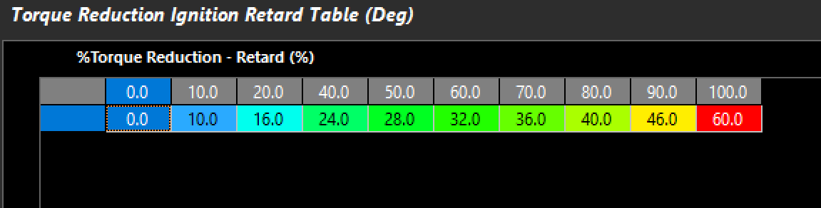
Torque Reduction Ignition Retard
Any function of ignition retard in the ECU will have an affect on engine torque.
During a Torque Reduction request the ECU can Retard the ignition timing to reduce Torque.
This setting indicates to the ignition timing retard in degrees vs the requested %Torque Reduction - Retard.
Example.
- Engine %Torque Reduction - Retard = 50%.
- 28 degrees retard applied
- This should reduce torque 50%
These values need to be validated using a dyno to teach the ECU how much retard will actually reduce torque %
** Engine design (bore/stroke/compression, etc) will wildly affect this table - and it must be validated with a dyno

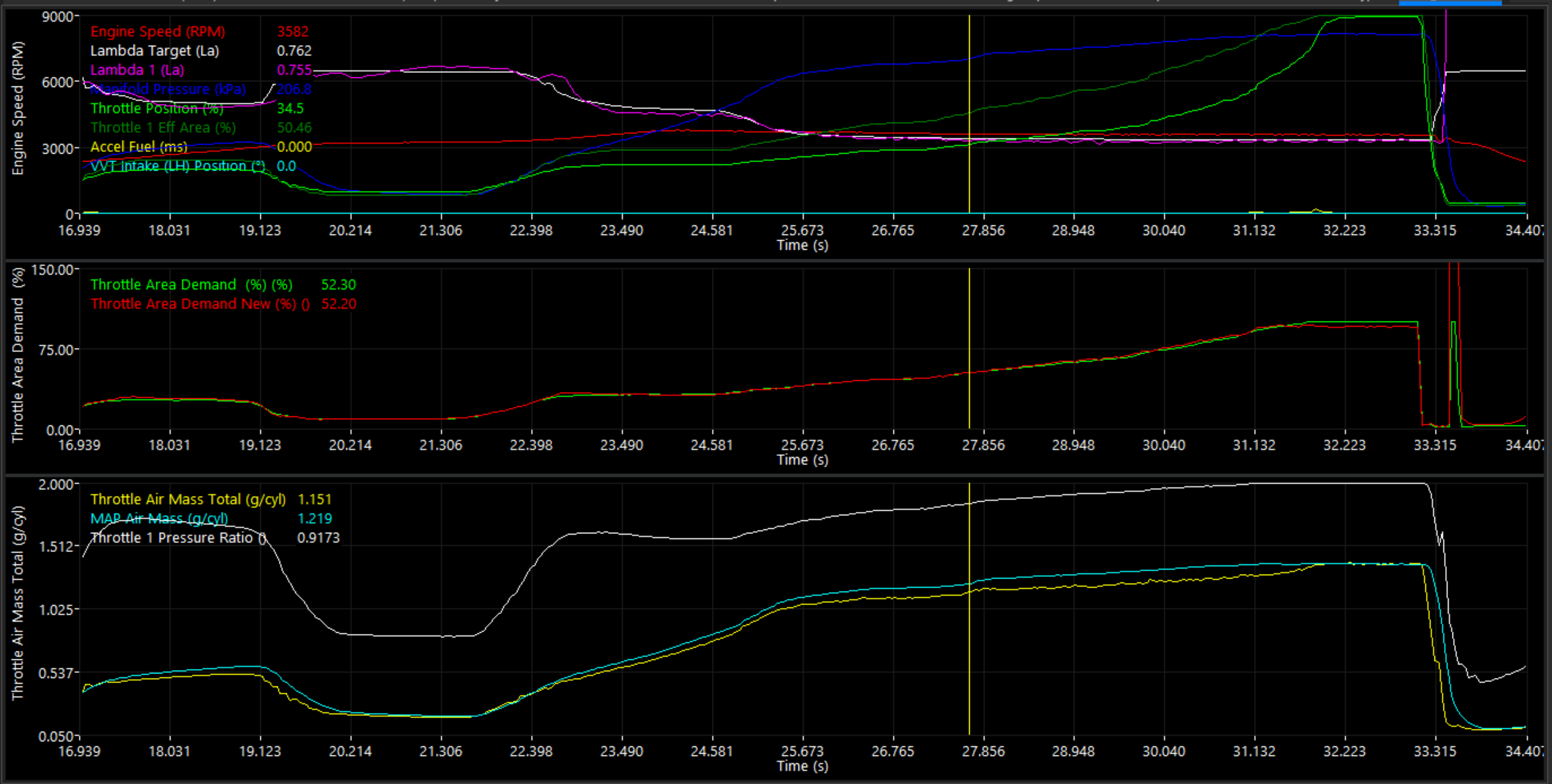
Example shows %Torque Reduction - Retard (%) bringing Engine Torque down to Launch Torque Target. Top Plot shows delta of Ignition Base vs actual Ignition Angle. ** Torque control through throttle transitioning and MAP pressure change for Launch Control
Runtime - Torque Reduction - Retard (NM) :
Any compensation for ignition angle subtracting from the "Ignition Base Angle" value, is considered "Torque Reduction - Retard", and translated into "NM" via "Torque Reduction Ignition Retard" table (below). Ignition Angle Base could be considered MBT Ignition Value in some cases depending on the tuning strategy being utilized. 
Torque Reduction Throttle
Any function of reducing Throttle Area in the ECU will have an affect on engine torque.
During a Torque Reduction request the ECU can Reduce the Throttle Area to reduce Torque.
Torque reductions via throttle must be validated either via the Dyno, or using the ECU calculated torque channels.
A comparison of Engine Torques can be used to validate throttle body area
** Improperly calculated Engine Torque channels will contribute to severe error in the Throttle Area table
This could be a result from error in the fuel model, or calibration (lambda actual vs lambda target
** Outflow function becomes active when TMF pressure ratios are close to unity. This allows the ECU to calculate airflow at these times, and the scaler should be set. It allows the ECU to calculate TMF Torque values which are critical to Throttle Area Torque reductions, etc.


A correctly configured TMF outflow scaler at full throttle (torque matching)
** Testing at heavy load ensures the outflow scaler is in its functional range, and then can be compared to properly calculating channel like Engine Torque (Uncorrected) (Nm) in this example
Comparing validated torque channels can be done various ways. Sweeping the throttle throughout it's range, or by temporarily using the Pedal to Throttle Area Demand Translation Clamp table :
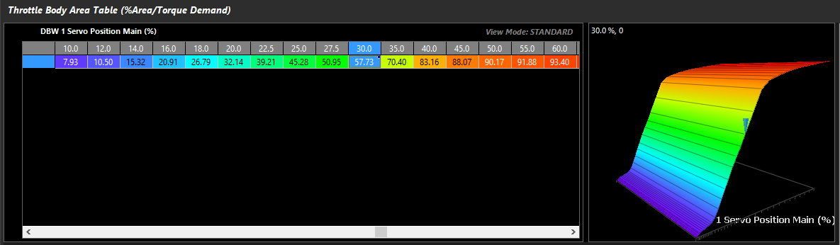
Error in throttle air mass can be corrected in the Throttle Area Table
Validating Throttle Area Torque (Engine Torque - TMF)

Entering a NM value in to the "Calibrate Throttle Area" section will clamp the throttle for validation.
With a properly "taught" Engine Torque TMF, Throttle Area table, Frictional Loss, and Torque Calculations, the ECU will have the ability to control RPM speed targets easily, and target torque through a number of features such as Launch Control, Traction Control, Ground Speed Limiting, RPM Limiting, and more .

Example of Launch RPM control at exactly 4000rpm with a tuned setup, with nearly exact torque targeting