VDC Setup
VDC Setup
Nissan Vehicle Dynamic Control (VDC)
The Nissan Vehicle Dynamic Control (VDC) uses various sensors to monitor driver inputs and vehicle motion.
The system takes control of braking and control of the engine output to achieve optimal performance, whilst keeping the vehicle on the steered path.
It is extremely important that the engine management system integrates seamlessly to achieve the correct functionality.
The Emtron R35 GT-R Plugin ECU is designed to replicate the OEM engine torque output by accepting and abiding by torque requests from the VDC system.
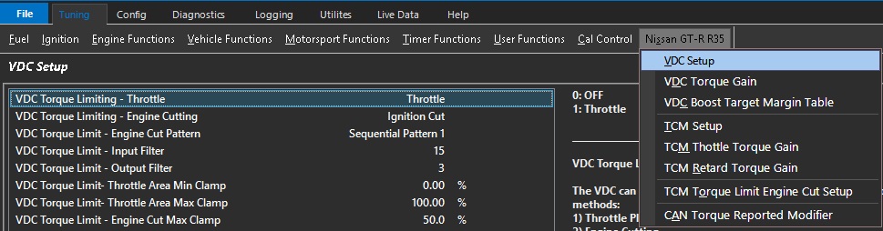
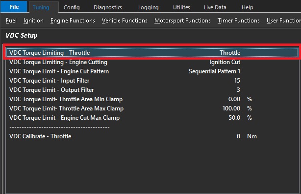
VDC Torque Limiting - Throttle
The VDC can request a Nm Torque Reduction/Limit using a combination of 2 methods:
1) Throttle Plate Area control (TMF)
2) Engine Cutting
These are separate requests sent over the CAN Bus from the VDC module to the ECU. The ECU then
uses a series of calculations to convert the Torque reduction request into either Throttle Plate position
or/and Engine Cut percentage.
The VDC primary Torque Limiting is done by using the Throttle Plate. The ECU uses Throttle Mass
Flow calculations to derive the required Throttle Area for a given Torque Target.
In some situations this may be insufficient to limit Engine Torque so a blend of Throttle Area
reduction and engine cutting maybe required.
CAUTION: When selected to OFF, the ECU will ignore the Torque Limit Throttle requests from the VDC module.
Default: Throttle.
0: OFF
1: Throttle
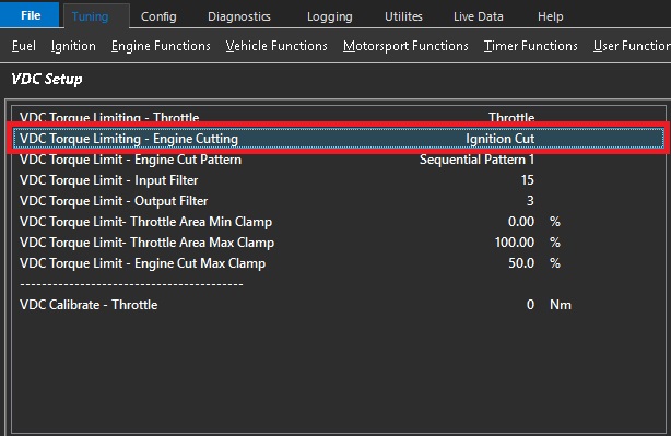
VDC Torque Limiting - Engine Cutting
The VDC can request a Nm Torque Reduction/Limit using a combination of 2 methods:
1) Throttle Plate Area control (TMF)
2) Engine Cutting
These are separate requests sent over the CAN Bus from the VDC module to the ECU. The ECU then
uses a series of calculations to convert the Torque reduction request into either Throttle Plate position
or/and Engine Cut percentage.
The VDC secondary Torque Limiting is done by Engine Cutting.
A VDC Torque Limit (Nm) using Engine Cutting gets converted by the ECU into a calibrated
Engine Cut percentage using the following parameters:
- Engine Ideal Torque
- Frictional Loss
- Torque Reduction Cut Gain Table
CAUTION: When selected to OFF, the ECU will ignore the Torque Limit Cut requests from the VDC module.
Default: Ignition Cut.
0: OFF
1: Ignition Cut
2: Fuel Cut
3: Ignition + Fuel Cut
VDC Torque Limit - Engine Cut Pattern
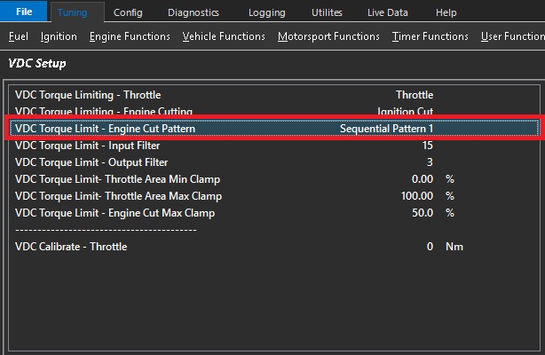
Used when VDC Torque Limiting is controlled with Engine Cutting.
Allows the cutting pattern to be selected.
All patterns will achieve the calculated torque and will simply affect the cylinder order of cutting.
Default: Sequential Pattern 1
0: Random Pattern 1
1: Random Pattern 2
2: Sequential Pattern 1
3: Sequential Pattern 2
VDC Torque Limit - Input Filter
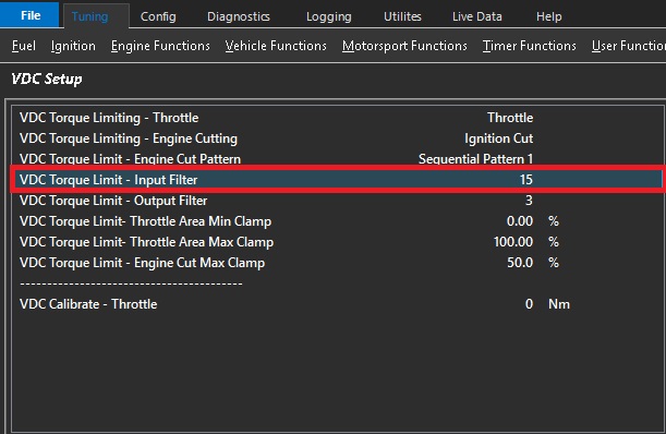
A VDC Torque Limit (Nm) gets converted by the ECU into a Throttle Area output called "Throttle Area Demand - VDC".
The ECUs uses complex Throttle Mass Flow calculations which are influenced strongly by the Pressure Ratio inputs before
and after the throttle plate. This filter gets applied to this ratio and is used to smooth the input torque requests.
0 = OFF (more aggressive VDC Control)
15 = Max Filtering
VDC Torque Limit - Output Filter
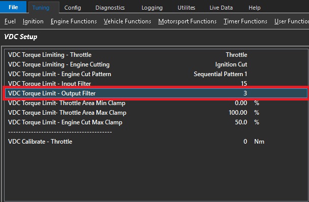
A VDC Torque Limit (Nm) gets converted by the ECU into a Throttle Area output called "Throttle Area Demand - VDC".
The output (Throttle Area) can be filtered by adjusting this setting before its used to control the Throttle Plate Area.
0 = OFF (more aggressive VDC Control)
5 = Max Filtering
Plot "Throttle Area Demand %" (filtered value) vs "Throttle Area Demand - VDC" (raw unfiltered) for tuning and to see
the filtering effects.
This can be used to smooth the throttle area demand %.
Increasing the filter will smooth the throttle demand.
However it is important to understand that any filter will reduce the response of the system.
VDC Torque Limit- Throttle Area Min Clamp
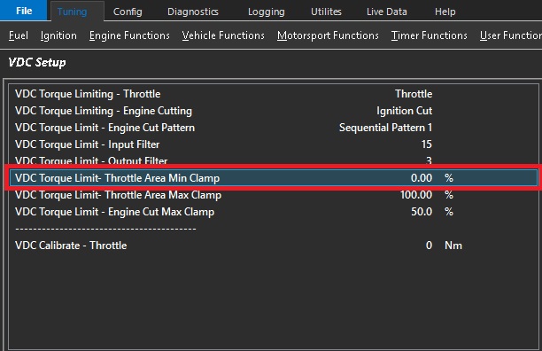
The VDC Torque Limit (Nm) with Throttle Plate control uses Throttle Mass
Flow calculations to derive the required Throttle Area for a given Torque Target.
This setting controls the Minimum amount of Throttle Area the ECU can apply for a given Torque Limit request.
0% = OFF
Example.: 60%
This means the Throttle Area is clamped between 60% and Max%
This is the minimum throttle area % that the system can apply during the VDC event.
Increasing this will cause the VDC system to favor more cutting to reduce torque to the request target.
An extreme of this setting would be 100% which means the throttle is not able to reduce.
VDC Torque Limit- Throttle Area Max Clamp
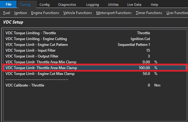
The VDC Torque Limit (Nm) with Throttle Plate control uses Throttle Mass
Flow calculations to derive the required Throttle Area for a given Torque Target.
This setting controls the Max amount of Throttle Area the ECU can apply for a given
Torque Limit request.
0% = OFF
Example.: 90%
This means the Throttle Area is clamped between Min% Value and 90%.
This should be set to 100% and require no adjustment in all known applications.
VDC Torque Limit - Engine Cut Max Clamp
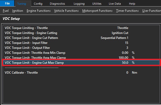
A VDC Torque Limit (Nm) using Engine Cutting gets converted by the ECU into a calibrated
Percentage
This setting controls the Maximum amount of Cut the ECU can apply for a given
Torque Limit request.
Example.: 50%
This means the Maximum Cut applied to the Engine will be clamped to 50%
This is set to 50% by default
Note: In situations where the torque is unable to meet the request target fast enough or at all, this setting would need to be increased. Lowering this setting will cause the VDC system to favor more throttle reduction.
VDC Calibrate - Throttle
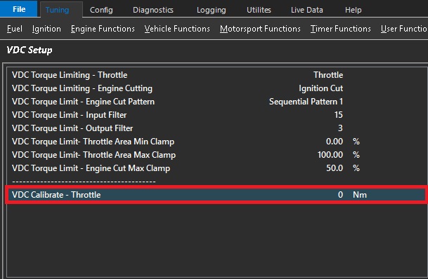
**CAUTION** The setting will override the Throttle Plate control and reduce the Throttle Area to achieve the entered Torque value.
The setting allows the VDC system to be calibrated and should be done so in a controlled environment only and preferably on a dynamometer.
ONLY becomes active when VDC Calibrate Throttle Area < Pedal Throttle Area Request
0 = OFF